Smd magnetic buzzer driver circuit selection method and principle
 Jan 17, 2023|
 View:428
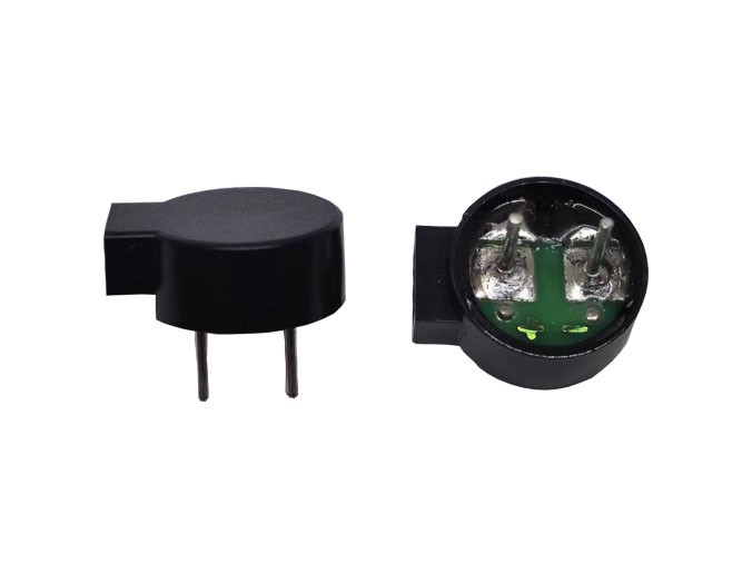
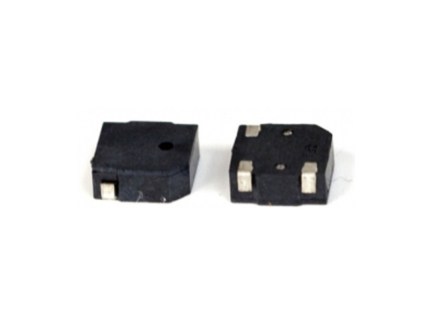
The smd magnetic buzzer is an electronic device that emits sound. The principle is similar to that of a relay, in which an electromagnet is energized to attract the oscillation of a diaphragm to produce an audio signal, thereby emitting sound. In this article, we will take you through the selection method and principle of smd magnetic buzzer driver circuit in detail.

Before talking about the smd magnetic buzzer driver circuit, we first need to understand the classification of the smd magnetic buzzer.
(1) The smd magnetic buzzer can be divided into electromagnetic smd magnetic buzzer and piezoelectric smd magnetic buzzer according to the different principles of sound generation.
(2) According to the different driving methods can be divided into active smd magnetic buzzer (internal driving line) and passive smd magnetic buzzer (external driving).
The electromagnetic smd magnetic buzzer and the piezoelectric smd magnetic buzzer contain active and passive smd magnetic buzzers. The word "source" here does not refer to the power supply but to the oscillation source. In other words, the active smd magnetic buzzer has an internal oscillation source, so it will be called as soon as the power is applied. And passive internal without the oscillation source, so if you use a DC signal can not make it chirp. A square wave of 2K~5K must drive it. Active smd magnetic buzzers are often more expensive than passive ones because of the multiple oscillation circuits inside.
Since the principle of piezoelectric smd magnetic buzzer and electromagnetic smd magnetic buzzer are different, their driving circuits are also different.
(1) For a piezoelectric smd magnetic buzzer, since its principle is to use the piezoelectric effect of the piezoelectric material to make sound, it can make sound by passing DC (active smd magnetic buzzer) or a certain frequency of AC (passive smd magnetic buzzer).
The MCU supplies power to the smd magnetic buzzer by controlling the on/off of the triode. If the smd magnetic buzzer is an active smd magnetic buzzer, the triode is turned on to make the smd magnetic buzzer sound; if it is a passive smd magnetic buzzer, the MCU needs to control the triode to turn on and off at a certain frequency to make the smd magnetic buzzer sound.
(2) For the electromagnetic smd magnetic buzzer, the smd magnetic buzzer is equivalent to an inductor because of the electromagnetic induction principle. Suppose it is an electromagnetic passive smd magnetic buzzer when the transistor changes from on to off. In that case, the smd magnetic buzzer will generate an inductive electromotive force, impacting the electronic components and may seriously damage the electronic components. Hence, a reverse diode needs to be connected with the smd magnetic buzzer to carry out a renewal (to give the inductive electromotive force a release path) to weaken the damage to the electronic components, especially for the passive electromagnetic smd magnetic buzzer.
The impact is insignificant for active electromagnetic smd magnetic buzzers because the triode does not need to be turned on and off frequently. Since the smd magnetic buzzer is a flow-controlled device, it requires using a triode as a switching tube to control the on/off. The use of NPN or PNP transistors is possible. Different types of transistors are available. Only the high and low levels for controlling their on/off are different.
In general, the driver circuit of the smd magnetic buzzer is relatively simple. Just follow the principle of different smd magnetic buzzers to choose a different driver circuit.
The above is about the smd magnetic buzzer driver circuit selection method and principle. If you need a more detailed understanding, welcome to contact us!