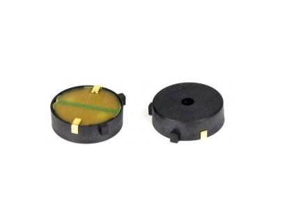
Does a 9v piezo buzzer need a resistor?
 Oct 23, 2026|
 View:4093
When connecting a 9V piezo buzzer to an electronic circuit, one common question is whether a resistor is required to protect the component. Adding the wrong resistor can reduce sound output or prevent the buzzer from operating as intended, while applying an unsuitable voltage can damage a component or its driver circuit.
The correct answer depends on the buzzer's design, its rated electrical specifications, and how it is driven. This guide explains when a resistor may be useful, how to evaluate its value and power rating, why active and passive piezo buzzers behave differently, and what to check before powering a 9V piezo buzzer.
Key Takeaways
A 9V piezo buzzer does not automatically require a series resistor. The exact model datasheet and circuit design determine whether one is needed.
An active buzzer normally contains an oscillator, while a passive piezo element generally needs an external alternating or pulsed drive signal.
A resistor can limit current or reduce drive under suitable circuit conditions, but it is not a universal solution for excessive supply voltage.
Ohm's law and resistor power calculations are useful only when the relevant voltage drop and current assumptions are valid for the circuit.
Testing, suitable driver selection, environmental considerations, and safe wiring help verify reliable operation.
Does a 9V Piezo Buzzer Need a Resistor?
A 9V piezo buzzer may operate without an additional series resistor when it is designed for the applied supply or drive signal and the manufacturer's circuit recommendations permit direct connection to the selected driver. Other circuits may require a resistor or a different driver arrangement to meet current, voltage, sound-level, or control requirements.
The term “9V piezo buzzer” alone is not enough to determine the answer. Some products are complete active buzzers designed for a specified DC supply. Others are passive piezoelectric sounders specified by their drive voltage, frequency, capacitance, or other electrical characteristics. A component marked 9Vp-p, for example, should not automatically be treated as equivalent to a buzzer rated for a 9V DC supply.

How a Piezo Buzzer Works
A piezo buzzer uses the piezoelectric effect to convert electrical excitation into mechanical vibration. When an appropriate electrical signal is applied to the piezoelectric material, it changes shape slightly. The resulting vibration moves the surrounding air and creates audible sound.
A piezoelectric element is generally a capacitive load rather than a simple fixed resistor. Its electrical behavior changes with drive frequency and circuit conditions. This is why a basic resistance calculation cannot always describe the current flowing through a piezo element, particularly when it is driven by an alternating waveform.
Active Piezo Buzzer vs. Passive Piezo Buzzer
| Feature | Active Piezo Buzzer | Passive Piezo Buzzer or Element |
|---|---|---|
| Oscillator | Normally has a built-in oscillator | Usually relies on an external oscillating signal |
| Typical input | Specified DC supply | Specified AC, square-wave, or pulsed drive signal |
| Need for an external resistor | Depends on the product and driver circuit | Depends on the element, drive circuit, and intended output |
| Tone control | Often limited by the internal oscillator | May allow external control of tone frequency |
| Key check | Rated supply, polarity where applicable, and current requirements | Drive amplitude, frequency, waveform, and component limits |
What Does a Resistor Do in a 9V Piezo Buzzer Circuit?
1. Limiting Current in an Appropriate Circuit
A resistor can limit current when it is placed in a circuit whose behavior is suitable for resistive current limiting. This can be important for protecting a driver or setting an operating condition. However, a piezo element's capacitive behavior means that current depends on the drive waveform, frequency, and impedance of the complete circuit. A resistor should therefore be selected from the actual circuit requirements rather than from the 9V label alone.
2. Reducing the Voltage Applied to a Load
A resistor can create a voltage drop when current flows through it. The amount of that drop is not fixed: it changes with current. As a result, a series resistor does not behave like a regulated voltage converter. If the supply exceeds the buzzer's maximum permitted voltage, a suitable regulator or driver designed for the application may be more appropriate.
3. Adjusting Sound Output
Some circuit designs use additional components to change drive conditions and sound output. Reducing the signal applied to a piezo element can reduce its acoustic output, but the relationship depends on the component and circuit. A resistor that is too large may make the sound weak, alter the waveform, or prevent the desired behavior.
The manufacturer's application notes should take priority over generic circuit suggestions. Some piezoelectric sound components have specific recommendations for volume control and explicitly warn against placing a resistor in series with the supply because it can affect oscillation. The circuit must be matched to the exact buzzer design.
How to Calculate a Resistor Value
Ohm's law expresses the relationship between voltage, current, and resistance:
V = I × R
For a circuit where a known voltage must be dropped across a resistor at a defined current, the resistance can be estimated using:
R = VR / I
Here, VR is the voltage intended to be dropped across the resistor, and I is the current under the relevant operating condition. This calculation is appropriate only when the current assumption is valid for the load and circuit. It should not be applied blindly to a piezo element as though the element were a simple fixed resistance.
Example of a Voltage-Drop Calculation
If a circuit has a known 3V voltage drop across a resistor and a valid design current of 10mA, the calculated resistance is:
R = 3V / 0.01A = 300Ω
This is an illustration of Ohm's law, not a recommended resistor value for a 9V piezo buzzer. The actual voltage drop and current must come from the selected circuit and its component specifications.
Calculate Resistor Power Dissipation
A resistor also converts electrical energy into heat. For a resistor carrying a known current, its power dissipation can be calculated using:
P = I² × R
The selected resistor's power rating should exceed the calculated dissipation by an appropriate design margin, accounting for ambient temperature and the conditions specified by the resistor manufacturer. If the current or voltage across the resistor has not been established correctly, the power calculation will also be unreliable.
Key Resistor and Circuit Parameters
| Parameter | What It Means | What to Check |
|---|---|---|
| Supply voltage | The voltage provided by the circuit | Confirm that the buzzer and driver can operate at this voltage. |
| Rated voltage | The manufacturer's specified voltage condition | Check whether it refers to DC supply, peak-to-peak drive, or another condition. |
| Current | Electrical current drawn under defined conditions | Use relevant datasheet values or valid circuit measurements. |
| Resistance | Opposition to current in a resistive component | Calculate from a known resistor voltage drop and valid current assumption. |
| Power rating | The power a resistor can dissipate under specified conditions | Allow a suitable margin for temperature and operating conditions. |
| Tolerance | The permitted variation from the nominal resistance value | Choose a tolerance suitable for the circuit's requirements. |
| Resistor type and package | The physical format and construction | Check PCB layout, assembly process, temperature, and power requirements. |
Where Should the Resistor Be Connected?
In a circuit designed for series current limiting, a resistor is placed in the current path so that the intended current also passes through the resistor. However, the correct position depends on the driver topology and the buzzer manufacturer's circuit recommendation. A circuit designed for a piezo element may differ from one intended for an active buzzer with an internal oscillator.
Before changing the circuit, identify the buzzer's terminals, supply polarity if relevant, and the driver's output configuration. Follow the datasheet's reference circuit where one is provided. Do not assume that placing a resistor directly in series with the power supply is appropriate for every piezoelectric sound component.
Review the product's rated voltage, drive method, dimensions, and acoustic requirements before finalizing the design.
Explore Piezo Buzzer ProductsHow to Test a 9V Piezo Buzzer Circuit Safely
1. Check the Datasheet and Wiring
Confirm the model number, rated voltage, operating conditions, terminal identification, and recommended drive circuit. Check for loose wires, solder bridges, incorrect polarity where applicable, and accidental shorts before applying power.
2. Verify the Power Supply
Measure the supply voltage using an appropriate multimeter and confirm that it remains within the permitted range. A supply labelled 9V may not deliver exactly 9V under every condition, particularly when battery voltage changes with state of charge or load.
3. Check the Driver and Resistor
If the circuit uses a resistor, verify its nominal value, tolerance, package, and power rating. Confirm that the driver can handle the buzzer's electrical load. For a passive piezo element, also verify the drive frequency and waveform rather than testing it with an unsuitable steady DC connection.
4. Test Sound Output Under Consistent Conditions
Operate the buzzer within its rated conditions and listen for a clear, stable tone. If acoustic output needs to be measured, use a consistent distance, mounting arrangement, and background environment. Compare results with the manufacturer's stated test conditions instead of assuming that every measurement should match a catalogue value exactly.
5. Consider Environmental Conditions
Temperature, humidity, mounting, enclosure design, and vibration can affect circuit behavior or perceived sound. Confirm the operating limits of both the buzzer and the resistor. Environmental protection should be based on the actual product specification, not inferred from the component's appearance.
Common Problems and Troubleshooting
| Symptom | Possible Cause | Recommended Check |
|---|---|---|
| No sound | Incorrect wiring, unsuitable drive method, missing signal, or voltage mismatch | Verify the model, power supply, terminals, and required drive waveform. |
| Sound is too weak | Excessive series resistance, unsuitable frequency, mounting effects, or insufficient drive | Compare the circuit against the datasheet and test under consistent conditions. |
| Intermittent sound | Loose connection, unstable supply, or an unsuitable drive circuit | Inspect wiring and supply stability, then verify the driver configuration. |
| Resistor becomes too hot | Excessive power dissipation or an incorrect design assumption | Recalculate power from the actual voltage and current and check the rating. |
| Unexpected tone or oscillation | Incorrect drive frequency or a circuit that conflicts with the buzzer's design | Check the recommended drive signal and manufacturer application guidance. |
Choosing a 9V Piezo Buzzer for an Electronic Product
A resistor decision should be part of the broader component-selection process. Engineers and purchasing teams should evaluate the electrical interface, expected sound output, available PCB space, assembly method, and environmental requirements together.
Electrical compatibility: Confirm the exact supply or drive-voltage specification and the required driver circuit.
Sound output: Review the rated sound pressure level, frequency, and measurement conditions.
Dimensions: Confirm diameter or package size, component height, and PCB footprint.
Mounting: Determine whether a surface-mount or another mounting format suits the production process.
Environment: Check the documented operating-temperature and moisture-protection requirements.
Documentation: Request the exact model datasheet and reference circuit before production approval.
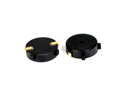
9V SMD Piezo Buzzer
Shenghui Electronic lists a 9V SMD piezo buzzer model with dimensions of Φ17.0 × 5.0 mm, a listed drive specification of 9Vp-p, a frequency of 4 kHz, and a sound pressure level of 85 dB. These are model-specific catalogue details; the complete datasheet should be checked before circuit integration.
When assessing resistor requirements, confirm the model's electrical specification and recommended drive method instead of selecting a resistor based only on the product's 9V description.
View 9V Piezo BuzzerConclusion
A 9V piezo buzzer does not always need a resistor. The correct circuit depends on whether the component is an active buzzer or a passive piezo element, how it is driven, and the manufacturer's rated electrical conditions. A resistor may be appropriate in a specific design, but it should not be treated as a universal protection component or a substitute for a correctly matched power supply.
Before powering a circuit, verify the model's datasheet, calculate resistance and power only from valid circuit assumptions, check driver compatibility, and test the buzzer under controlled conditions. These steps help prevent voltage mismatches, weak sound output, overheating, and avoidable component failures.
For businesses looking for a reliable 9V piezo buzzer manufacturer, Shenghui Electronic offers piezo buzzer models in different configurations and package sizes. Buyers can review the product specifications and contact Shenghui Electronic to discuss the electrical and acoustic requirements of their applications.
Share the required voltage, drive method, sound output, dimensions, and operating environment to help identify a suitable product configuration.
Get a Quote / Contact UsFrequently Asked Questions
Does every 9V piezo buzzer need a resistor?
No. The need for a resistor depends on the buzzer's design, rated voltage, drive circuit, and manufacturer recommendations. Some models can operate with a suitable supply or driver without an additional series resistor. Always check the exact model datasheet before adding components.
Can a resistor protect a piezo buzzer from excessive voltage?
A resistor can create a voltage drop when current flows, but the drop changes with the circuit current. It is not equivalent to a regulated supply and may not provide reliable protection for every piezo buzzer. Use a suitable regulator or driver when the supply does not meet the component's rated requirements.
How is the resistor value calculated?
For a valid resistive voltage-drop calculation, use R = VR / I, where VR is the voltage across the resistor and I is the applicable current. A piezo element is generally capacitive, so its drive current cannot always be treated as a fixed resistive current. Use the actual circuit specifications.
What resistor power rating is required?
Calculate the resistor's expected power dissipation using valid voltage and current values. For a known current, P = I²R. Choose a resistor with a suitable power rating and operating-temperature margin. If the actual current or voltage drop is unknown, the power rating cannot be selected reliably.
Can a 9V piezo buzzer be connected directly to a microcontroller?
Not automatically. The connection depends on the buzzer's drive requirements and the microcontroller's output limits. A compatible passive element may need an oscillating signal, while an active buzzer generally needs its specified supply. A transistor or dedicated driver may be required when direct drive is unsuitable.
Why does a piezo buzzer sound weak after adding a resistor?
The resistor may be reducing the effective drive, or the circuit may not match the buzzer's recommended operating method. The result also depends on drive frequency, waveform, mounting, and enclosure design. Check the datasheet and compare the circuit with the manufacturer's recommended reference design.